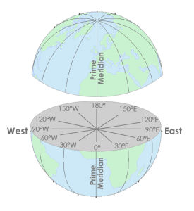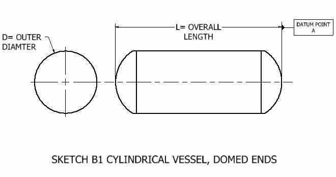
Once the datum has been selected, all moment arms and the location of permissible c.g. The datum is established by the manufacturer. "Datum (reference datum)-is an imaginary vertical plane or line from which all measurements of arm are taken. Here is the official FAA definition of the Datum Line. The Datum line you guys are talking about isnt called a datum line its some other reference line that I would agree with what Mike explained it as though I personally didnt know what it was called but knew it wasnt a datum line. And it always seems to follow in a line along the widest part of the fuse formers which is very helpful when Lofting your fuse formers and has nothing to do with CG or its location. From what I always was told is the datum line was basically a Horizontal reference line that followed the thrustline on the plane. Ok U guys cornfusing me on the Datum Line. Again, this is not necessary for small models but when you have something cracking the 55# limit, it's not a bad idea. It give a complete description of the weight and balance process. Search for AC91-23A, Weight and Balance for Pilots. The FAA website (faa.gov) has the Advisory Circular available for free. Divide the moment by the total weight and you will then have the location of the c/g. When you have recorded each moment, total them up. Record the weight on each scale referencing the distance you measured. It dosen't matter whether the airplane has a nose or tail wheel. Measure from this line to the center line of each gear leg. Mark this with a line perpendicular to the longitudinal axis of the airplane. Level the aircraft and suspend the plumb bob at your datum point. You would need three decently calibrated scales, a plumb bob and tape measure. The basic calculation is W/A=M or Weight times Arm equals Moment. The most common locations can be anywhere from the nose to the wing leading edge. If you still have questions, please write in the comment section, and I will be happy to help.As Starcad said, the datum is an arbitrary vertical line used for c/g calculations. I hope I could able to give enough ideas on profile tolerance. When profile tolerance is used, no other dimensions are shown for that profile, became if there are datums, you may use basic dimensions. Unless it is essential, we should refrain from using profile tolerance. Please note that profile tolerance increases part cost as suppliers need special machines like CMM to measure profile tolerance. Now a day profile tolerance is used in almost every industry. But that does not mean that only these two industry uses profile tolerance. Profile tolerance is beneficial in industries like automobiles and aerospace as these industries use complex shape parts. What is the datum target and why it is useful Conclusion: GD&T profile tolerance
Datum line definition how to#
What is bonus tolerance and how to calculate bonus tolerance
Datum line definition software#
There is a software called PolyWorks which is very good to do this kind of task. So CMM data points are compared with the CAD data to check any deviations. Nowadays, all designs are made in CAD software. The CMM can scan the data points and match them with what is shown in the drawing. But if the surface is complex, then CMM ( Coordinate measuring machines) is used. If it’s a very simple surface, then a height gauge can be used to measure profile tolerance. In the case of a line, every point of that line should be in between that tolerance zone. It can also be in the opposite direction, but it can not be in both directions.Įvery point of all true surfaces should be in between that tolerance zone.

See the below example where the profile tolerance is only in one direction. When the tolerance zone of a profile is in one direction, it is called Unilateral profile tolerance.


These are types of profile of a surface tolerance based on the direction of profile toleranceīilateral Profile tolerance can be further categorized as below The types of profile of a surface can be categorized based on the direction of variation and applicability of surfaces, This is what it means Types Of Profile Of A Surface Tolerance Due to machine or measurement variations, engineers should allow a deviation in the line elements or surfaces called profile tolerance. No surface can be made absolutely perfect. Profile tolerance is the amount of deviation of a profile of a line or a surface. What does letters a, b and c means in a profile tolerance? What is profile tolerance?.Profile Tolerance in between two points on a surface.Types Of Profile Of A Surface Tolerance.


 0 kommentar(er)
